Self-Contained Metering
Self-Contained Metering is required for the following services:
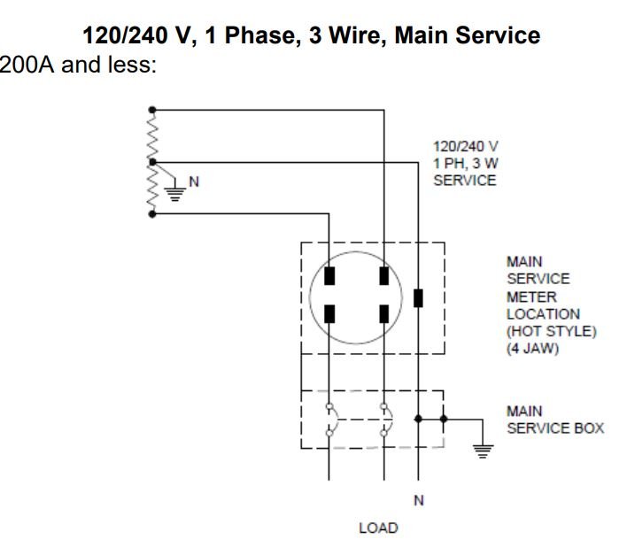
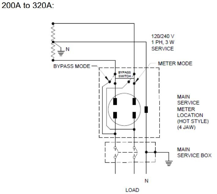
- 120/240V, 1PH, 3W:
– 200A or Less (main service offering for most residential customers).
– 200A to 320A (for larger residential customers).
Note: Over 320A, 1 phase service is using transformer rated metering socket,
refer to Section 5.1.1.
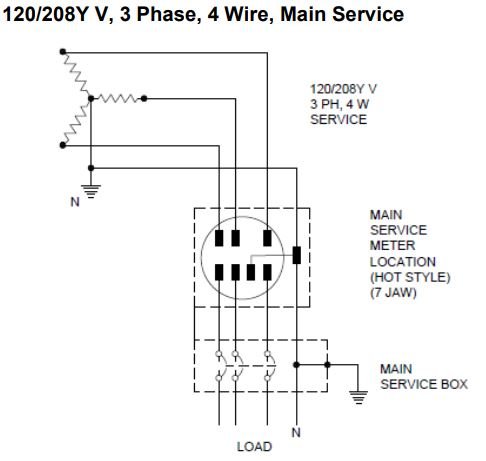
- 120/208V and 347/600V, 3PH, 4W:
– 200A or less.
Note: All three phase services with a load over 200A including any loads on
480V and 600V delta are using transformer rated metering socket, refer to
Section 5.1.2.
General
- a) The Customer shall supply the meter socket and sealing ring. They shall be
certified in accordance with CSA Standard C22.2 No. 115, Meter Mounting
Devices and they shall be approved by BC Hydro.
- b) The sealing ring shall be a screw type in accordance with section 6.2.
Ringless meter sockets are not permitted.
- c) The neutral terminal on 5 jaw meter sockets shall be in the 9 o’clock position.
Prior to 2005 the neutral terminal on some 5 jaw meter sockets was required to be in
the 6 o’clock position. When adding a new 5 jaw sub service meter socket to an
existing installation, the new meter socket neutral terminal shall be in the 9 o’clock
position, even if the existing neutral terminals are in the 6 o’clock position.
- d) The meter tilt shall not exceed 3° from vertical.
- e) Metered and unmetered conductors shall not be installed in the same
raceway, pull box or distribution gutter box.
- f) The supply service conductor conduit shall be continuous and without access
fittings or junction boxes on the line side of a meter socket, except where a
sealable LB fitting is used beside the Meter Socket.
- g) Line and load side conductors shall not be crossed in the meter socket.
- h) Where a 3 phase, 4 wire supply, serves a 3 phase, 3 wire load, a 7 jaw, 3
phase, 4 wire meter socket shall be installed and the neutral shall be extended
18 Requirements for Secondary Voltage Revenue Metering (750 V and less)
to the meter socket.
The neutral conductor:
- Shall be white and insulated; and
- Shall carry the same ampacity of the line conductor; and
- Shall not be smaller than No. 6 AWG and meet the minimum conductor
size rating of the meter socket neutral terminal.
- i) Any “collar-type” devices, including surge arrestors, generator transfer and/or
hook ups, transfer switches, etc. shall not be installed within the meter socket
or between the meter socket and the BC Hydro meter.
- j) Prior to the installation of the meter, the Customer shall provide a durable
temporary weather resistant cover over the meter socket opening.
- k) When the service is to be temporarily energized prior to the installation of
the meter, CSA approved jumper bars shall be installed in the meter
socket. Proper electrical and mechanical contact must be maintained
between the meter socket jaws and the meter terminal blades after the
removal of the jumpers.
- l) Underground service meter sockets shall be in accordance with section 6.1.
Overhead service meter socket dimensions are not specified since BC Hydro
does not install the conductors
BC Hydro approved meter sockets
Transformer Rated Meter Sockets
|
Combination Meter Socket and Breaker Panel
Service Type | Manufacturer | Model(s) |
120/240V, 1 Phase, 3 Wire, 400A with integral CT | Microlectric® | BP320-V-250B – OH, BP320-TV-250B – UG |
HYDEL | EK320RO2 | |
120/240V, 1 Phase, 3 Wire | Leviton | LS810-BRC (100A), LS820-BRC (200A) |
|
|
|
Individual Meter sockets
Meter Socket Cover Removal
Removal of the meter socket cover shall not be possible unless the following
sequence is followed:
- Removal of the sealing ring.
- 200A service – removal of the 200A meter
320A service – meter shall be removed manually when the switch is in “By-Pass Mode”.
- Operation of the meter socket cover latch.
- Removal of the meter socket cover.
Configurations that rely on seals, in addition to the BC Hydro sealing ring seal, or
padlocks to prevent removal of the meter socket cover are not permitted.
Mounting Height
- a) The meter’s centre line shall be 1500 mm to 1800 mm above finished grade
- b) If the Customer intends to build up the grade after the meter has been
installed, a platform or ramp shall be provided during the interim period. The
platform shall not be less than 900 mm by 900 mm.
Enclosures for Permanent Meter Sockets (Kiosk)
- a) Installation of permanent meter socket within enclosure is atypical and used
where the meter may be subject to vandalism and accidental damage where
it reasonably cannot be alleviated. Enclosures are subject to the following requirements:
- The enclosure has a hinged door; and,
- The enclosure and door do not interfere with the installation, reading or removal of the meter;
- The enclosure and door do not interfere with the installation or removal
of the meter socket cover; and,
- The clearance of 254-305 mm (10-12 inch) is provided between the
inside of the closed enclosure door and the meter socket cover; and,
- The enclosure has a 152-178 mm (6-7 inch) round or square Lexan or
20 Requirements for Secondary Voltage Revenue Metering (750 V and less)
equivalent Polycarbonate viewing window installed on the enclosure
door directly in-line with the front of the meter; and,
- For enclosures containing multiple meters, the viewing window should
be located approx. 1/3 of the way down from the top of meter stack
inside, geometrically centered across the stack. If this does not place
the window in front of the meter cluster, then re-center the window in
front of the meter cluster; and,
- The enclosure shall have a 16 mm (5/8 inch) hole which is,
- complete with tamperproof and weatherproof knockout plug on the
- enclosure roof; and,
- located as close as possible to the front of the enclosure and
- within 24-inch radius of the meter; and,
- at least 6 inches away from all edges.
- b) If it is proposed to lock the enclosure, the details of the locking should include
double padlocking provision as approved by local BC Hydro design.
- c) Kiosk meter center line is allowed to be 915 mm to 1800 mm above finished
grade.
Temporary construction power meter sockets may be installed within enclosure,
but the enclosure shall have a 16 mm (5/8 inch) hole which is complete with a
tamperproof and weatherproof knockout plug on the enclosure roof at least 6 inches
away from all edges.
Meters Mounted on Poles Meter sockets shall be located on the side of the pole that is not subject to vehicle damage. If this is not practicable, protection posts shall be installed 600 mm in front of the meter socket.
Prior the installation of the meters by BC Hydro:
- Each Customer suite address or suite number shall be permanently
and legibly marked on the interior of each meter socket, the exterior of
each meter socket cover, and the sub service disconnect device; and
- All suite doors, complete with their permanent address or suite
numbers, shall be installed; and
Where a 3 phase, 4 wire supply, serves a 3 phase, 3 wire load, a 7 jaw, 3
phase, 4 wire meter socket shall be installed and the neutral shall be extended
from the distribution gutter box to the meter socket.
The neutral conductor:
25 Requirements for Secondary Voltage Revenue Metering (750 V and less)
- Shall be white and insulated; and
- Shall carry the same ampacity of the line conductor; and
- Shall not be smaller than No. 6 AWG and meet the minimum conductor size
rating of the meter socket neutral terminal.
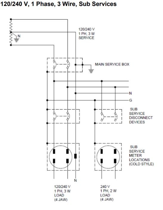
Schematic Diagrams
Self-Contained meter sockets shall be in accordance with the schematic drawings in this section. The drawings illustrate a “main service box”. In accordance with ES54, the protective device in the main service box shall be a breaker.